Band Pass Filter Response

Band pass filter response
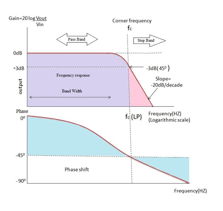
A band-pass filter admits frequencies within a given band, rejecting frequencies below it and above it. Figure 8.3 shows the frequency response of a band-pass filter, with the key parameters labelled. A stop-band filter does the reverse, rejecting frequencies within the band and letting through frequencies outside it.
What is frequency response of a band pass filter?
Generally, the dielectric band-pass filters can be used over the frequency range from 300 MHz to 100 GHz. For high-frequency applications, NRD waveguide filters (Figure 7.38) gain interests because of the extremely low-loss and low dielectric constant materials that can be used in the design.
What does a band pass filter do?
In a receiver, a bandpass filter allows signals within a selected range of frequencies to be heard or decoded, while preventing signals at unwanted frequencies from getting through. A bandpass filter also optimizes thesignal-to-noise ratio (sensitivity) of a receiver.
How is band pass filter calculated?
Band Pass Filter using R, L and C Components The centre frequency of the band pass filter which is also termed as 'resonant peak' can be formulated by using the below equation: fc = 1/2π√(LC) Where L = inductance of an inductor whose units are in Henry (H). C = capacitance of a capacitor whose units are in Farad (F).
What is passband and stopband?
Q: What is the passband and the stopband? A: Passband is the band of frequencies of the input signal that passes through the filter with an attenuation of less than 3 dB attenuation, while stopband is a band of frequencies of the input signal that are blocked or more highly attenuated by the filter.
What is band-pass filter and band reject filter?
A band-pass filter, in contrast, passes frequencies that fall only within a relatively narrow range, and a band-reject filter (also called a band-stop or notch filter) passes all frequencies except those that fall within a relatively narrow range.
What is band-pass frequency?
A passband is the range of frequencies or wavelengths that can pass through a filter. For example, a radio receiver contains a bandpass filter to select the frequency of the desired radio signal out of all the radio waves picked up by its antenna.
What is frequency response?
A frequency response describes the steady-state response of a system to sinusoidal inputs of varying frequencies and lets control engineers analyze and design control systems in the frequency domain. To understand why the frequency domain is important consider an acoustic guitar.
What is quality factor in band pass filter?
A band-pass filter can be characterized by its Q factor. The Q-factor is the reciprocal of the fractional bandwidth. A high-Q filter will have a narrow passband and a low-Q filter will have a wide passband. These are respectively referred to as narrow-band and wide-band filters.
Why is it called a band pass filter?
There are applications where a particular band, or spread, or frequencies need to be filtered from a wider range of mixed signals. Filter circuits can be designed to accomplish this task by combining the properties of low-pass and high-pass into a single filter. The result is called a band-pass filter.
How does a band pass filter is constructed?
A simple passive Band Pass Filter can be made by cascading together a single Low Pass Filter with a High Pass Filter. The frequency range, in Hertz, between the lower and upper -3dB cut-off points of the RC combination is know as the filters “Bandwidth”.
How is bandpass filter bandwidth calculated?
The bandwidth of the filter is therefore the difference between these upper and lower -3dB points. For example, suppose we have a band pass filter whose -3dB cut-off points are set at 200Hz and 600Hz. Then the bandwidth of the filter would be given as: Bandwidth (BW) = 600 – 200 = 400Hz.
How is pass band gain calculated?
| Frequency, ƒ ( Hz ) | Voltage Gain ( Vo / Vin ) | Gain, (dB) 20log( Vo / Vin ) |
|---|---|---|
| 5,000 | 1.96 | 5.85 |
| 10,000 | 1.99 | 5.98 |
| 50,000 | 2.00 | 6.02 |
What is bandwidth of a filter?
The 3 dB bandwidth of an electronic filter or communication channel is the part of the system's frequency response that lies within 3 dB of the response at its peak, which, in the passband filter case, is typically at or near its center frequency, and in the low-pass filter is at or near its cutoff frequency.
What is maximum passband ripple?
IIR Digital Filters Design a digital lowpass filter so that the passband ripple does not exceed 2 dB for up to ωp = 7870 rad s−1 and the stopband attenuation is greater than 50 dB for frequencies above 5ωp.
Is attenuation and ripple same?
the ripple is a certain amount of amplification or attenuation tolerated in the pass band of the filter. So it depends if those effects are critical for your application or not.
What is the difference between baseband and passband?
Baseband transmission sends the information signal as it is without modulation (without frequency shifting) while passband transmission shifts the signal to be transmitted in frequency to a higher frequency and then transmits it, where at the receiver the signal is shifted back to its original frequency.
Where is active band-pass filter used?
One typical application of a band pass filter is in Audio Signal Processing, where a specific range of frequencies of sound are desired while attenuating the rest. Another application is in the selection of a specific signal from a range of signals in communication systems.
Where are band reject filters used?
Band Reject Filter Applications
- The filter is used mainly in public address systems and speaker systems for ensuring good quality audio.
- The devices are a crucial part of telephone technology, as they are used as line noise reducers in case of signal transmission.
How do you reject a band filter?
To create band-pass and band-reject filters, you need two cutoff frequencies, a lower limit fL and a higher limit fH. The combined filters inherit the transition bandwidth (or roll-off), which might be different at each end, from the low-pass and high-pass filters that were used to build it.
12 Band pass filter response Images
Low Pass Filter Passive RC Filter Tutorial Filters Engineering

High and Low Pass Filter Circuit diagram Circuit Filters

CLICK PARA AMPLIAR Caixa de subwoofer Caixa do subwoofer de 12

How to make only bass circuit diagram low pass filter easy diagram

Design LowPass HighPass and BandPass Filters in Browser in Minutes
Passive Low Pass RC Filters Filters Passive Electronics

How to make only bass circuit diagram low pass filter easy diagram

Low pass filter for Subwoofer with 4558d IC Subwoofer Diy Subwoofer

the reading response checklist for readers

Offering Choice in your Reading Response Activities Top Teaching

In this Photoshop tutorial you will learn how to sharpen texture and
Post a Comment for "Band Pass Filter Response"